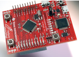
I received my TI Stellaris LM4F120 LaunchPad today. I am eager to start using it. For now, have a look at Joonas' page.
30
Oct
2012
I received my TI Stellaris LM4F120 LaunchPad today. I am eager to start using it. For now, have a look at Joonas' page.

25
Oct
2012
Joonas has assembled one of my, I mean, his password generator. Have a look at his blog.
I also received my PS2 breakout board along with my programmer board, have assembled both of them, and will test them soon. I also got some small alligator clips and put on the leads of my solar panel to test the USB charger I assembled earlier.
My current project is a 4-port, self powered, independant port power with over-current detection, USB hub. I beleive I have the Gerber files complete, but want to take another look to make sure. Will send to fab in a few days.
15
Oct
2012
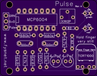
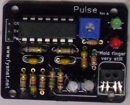
Here is my "Pulse" project fully assembled. It is very sensitive. A slight move of the finger and it skips a beat. I guess a few adjustments are in order. The camera sure was dark. I will have to see about getting some more light on the board next time.
I have 5v0 and Grn on the three pin header along with a "pulse" pin. When the light flashes, power is applied to this pin. This way, I can use my ATTINY2313 Breakout Board, put this pin on PB0 of the breakout board, then send this "pulse" through the USB to the host, calculating the pulse in BPM.
15
Oct
2012
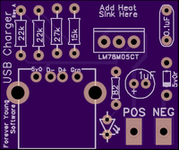
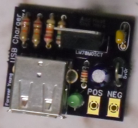
Here is my USB charger fully assembled. Now, all I need to do is change out the large car-battery gator clips on the solar panel for the smaller ones and try it out. I already put 9 volts to it and a volt meter on the other side, seemed to work fine, now for the real test, the solar panel and my phone...However, the sun must be out, right?
08
Oct
2012
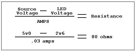
The easiest way to find if there is current on a board is to put an LED on it. However, you have to limit the amount of current to the LED or you will burn it up. To limit the amount of current, you can put a resistor just before or just after the LED. It is very simple to calculate how much ohms the resistor needs if you know the source voltage, the LED's voltage, and current (amps) used.
In the example below, we have 5v0 as the source voltage and an LED that is rated at 2v6 and uses 30mA. With this calculation, we know we need an 80 Ohm resistor. Since an 80 Ohm resister is not a common Ohm rating, you can always move to the next common rating, for example, 82 Ohms.
This is why you see an 82 Ohm resistor in most of my boards. I use LED's that use 2v6 and 30mA.
08
Oct
2012
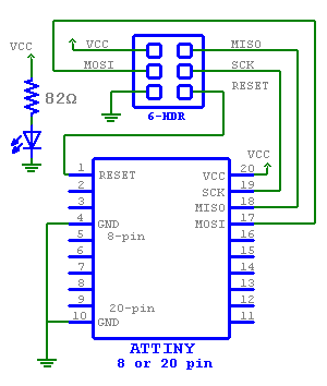
I got tired of wiring up my breadboard every time I needed to program one of my ATTiny 8- or 20-pin controllers. I have sent off to manufacturing a small simple PCB to make it a bit easier. If you are interested in one, let me know.

The scematic is as follows.
05
Oct
2012
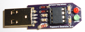
Here is the Password Generator assembled. Green LED lights when power is applied to the board, (board plugged in), and the red LED lights as the password is sent along the bus. I didn't have a smaller resistor for the 2k2 so I had to "force" a larger one, hence the offset. Let me know if you would like one; PCB only, PCB plus parts, or assembled, and if you need the firmware.
05
Oct
2012
I received the Password Generator and ATTiny2313 PCB's today. More later.
03
Oct
2012
My sample PIC18(L)F25K50's arrived today. Here are some of the USB features:
- USB V2.0 Compliant
- Crystal-less Full Speed (12 Mb/s) and Low-Speed Operation (1.5 Mb/s)
- Supports Control, Interrupt, Isochronous and Bulk Transfers
- Supports up to 32 Endpoints (16 Bidirectional)
- 1 Kbyte Dual Access RAM for USB
- On-Chip USB Transceiver
I will do some research and experiment with them a while and see about posting
some information and maybe a sample project.
03
Oct
2012
A few of the PCB's I ordered are back from the "fab's" and should be in my mail box with in
the next few days. I have already got a couple of orders for the
ATTINY2313 Breakout Board,
though if you are interested, please let me know. I now accept Paypal.
03
Oct
2012
I now have access to the Facebook page for USB: The Universal Serial Bus. I will also continue to update that page as I learn how to use Facebook. My children are teaching me :-)
01
Oct
2012
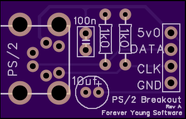
I have sent off to fabrication for a small PS/2 connector breakout board so that I can study the communication side of the ATTiny2313 and a Data/Clk device such as a mouse or keyboard. I will post again when I have completed the PCB and done some work with it.
