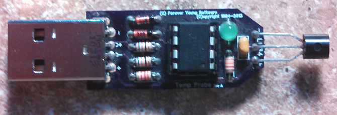
I decided to revisit an older project I started a while back. With the new parts from Newark, I was able to build a working model.

It uses the ADC (Analog to Digital Converter) of an ATTiny45 to measure the millivolts given by a LM34 temperature sensor. While doing this, the ATTiny45 waits for the host to request an HID report. Once found, it sends this information, letting the host convert to a Fahrenheit degree value.
It is a fairly simple build and shows how to use the ADC along with sending the data back to the host via the USB hardware. This blog post will show you what you will need to build it, how to build it, and then how to write the software (firmware) to accomplish this.
The Schematic and Parts List
This device requires very little parts and is fairly cheap to build.
1 - PCB, Perfboard, or Bread Board
1 - ATTiny45 (Newark or Mouser)
1 - 8-pin socket* (Newark or Mouser)
1 - LM34(DZ) (Newark
or Mouser)
1 - USB Connector (Newark or Mouser)
2 - 3.6 Volt Zener Diodes (Newark or Mouser)
1 - 100nf Cap (Newark or Mouser)
1 - 100uf Cap* (Newark or
Mouser)
2 - 68 Ohm resistor (Newark or Mouser)
1 - 2.2k Ohm resistor (Newark or Mouser)
1 - ??? Ohm resistor* (Be sure to correctly pair this resistor with you LED)
1 - Green LED*^ (Newark or Mouser)
*These items are optional
^The Newark LED draws a different current amount than the Mouser

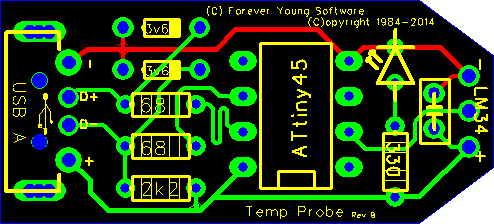
...and the screen shot of the FreePCB worksheet...

Notes: Be sure to correctly pair the resistor with the LED you buy. See LED's and Current Limiting Resistors.
The LM34 Temperature Sensor
The Three Pin Temperature sensor I use is the LM34(DZ), and outputs the current temperature in Fahrenheit degrees. To do this, it has an input of 5.0 volts on the power pin (from the USB), and outputs 10 millivolts for every degree on the signal pin. For example, if the room temperature is 77 degrees (F), the LM34 will output 770 millivolts. Now, how do we get this analog value sent to the ATTiny45? This is where the ADC comes in to play.
Notes: The LM34(DZ) I used here has the three pin TO-92 package, same as a generic transistor. When you place it on your PCB/Board, be sure to correctly orient the pins. If you place the Vcc pin in the Grnd hole, and the Grnd Pin in the Vcc hole, you will burn up the LM34 really quick.
The Analog to Digital Converter (ADC)
The ATTiny45 (and others in that family) contain an Analog to Digital Converter with one or more channels allowing multiple inputs. The ATTiny45 has four, though we will only use one for this project. The LM34 outputs an analog value in millivolts and we need a digital value. Therefore, if we give the ADC a range, 0 to 1023, and a voltage limit value, the ADC will return a digital value in that range.
For example, if we set the ADC to have a voltage limit of 5 volts, and the LM34 sends the ADC 770 millivolts, the ADC will return a value of 158. The 770 millivolts is at a range of 158 with a range from 0 to 1023, when that range has a limit of 5000 millivolts.
Therefore, our code can take that 158 value, knowing the range and voltage, and calculate that to 77 degrees.
(158 / 1024) * 5000 = 771.48 millivolts
Since we know that each 10 millivolts represents one degree, 771.48 millivolts divided by 10 = 77.148 degrees.
Notes: Depending on how you do your math, you can get different values for the millivolt value. For example, the calculation above used many decimal places to get 771.48. However, to get the 770 value mentioned, if you only use three decimal places from the divide, you get this 770 value.
(158 / 1024) = 0.154296875
(0.154 * 5000) = 770 millivolts
The Firmware
Our firmware indicates that it is an HID device and waits for a Request Report request from the host. When this request is received, our firmware does a conversion from the analog LM34 single to a digital range from 0 to 1023. Then sends this value as a 32-bit dword in the report buffer.
///////////////////////////////////////////////////////////////////////
#include <avr/io.h>
#include <avr/wdt.h>
#include <avr/interrupt.h>  // for sei()

#include <util/delay.h>     // for _delay_ms()

#include <avr/eeprom.h>
#include <avr/pgmspace.h>   // required by usbdrv.h

#include "usbdrv.h"

static uchar report_id;
static uint32_t report = 0;

// USB report descriptor
const PROGMEM char usbHidReportDescriptor[42] = {
  0x06, 0x00, 0xFF,     // USAGE_PAGE (Generic Desktop)
  0x09, 0x01,           // USAGE (Vendor Usage 1)
  0xA1, 0x01,           // COLLECTION (Application)
  0x15, 0x00,           // LOGICAL_MINIMUM (0)
  0x26, 0xFF, 0x00,     // LOGICAL_MAXIMUM (255)
  0x75, 0x08,           // REPORT_SIZE (8)

  // read state
  0x85, 0x00,           // REPORT_ID (0)
  0x95, sizeof(report), // REPORT_COUNT
  0x09, 0x00,           // USAGE (Undefined)
  0xB2, 0x02, 0x01,     // FEATURE (Data,Var,Abs,Buf)

  0xC0                  // END_COLLECTION
};

// -----------------------------------------------------------------
void buildReport() {
  // temperature (Fahrenheit) = millivolts / 10
  //  (LM34 returns 10 millivolts for each temperature)
  //   10mv =   1 Fahrenheit
  //  100mv =  10 Fahrenheit
  // 1000mv = 100 Fahrenheit

  // start the conversion
  ADCSRA |= _BV(ADSC);

  // wait until the ADC is done
  while (ADCSRA & _BV(ADSC))
    ;

  // read the value
  report = ADC;
}

usbMsgLen_t usbFunctionSetup(uchar data[8]) {
  usbRequest_t *rq = (void *)data;

  // HID class request
  if ((rq->bmRequestType & USBRQ_TYPE_MASK) == USBRQ_TYPE_CLASS) {
    report_id = rq->wValue.bytes[0];
    if (rq->bRequest == USBRQ_HID_GET_REPORT) {
      if (report_id == 0) {
        buildReport();
        usbMsgPtr = (void *) &report;
        return sizeof(report);
      }
    }
  }

  return 0;
}

static void myInit(void) {

  // ADMUX (17.13.1, page 134)
  //  bit    7     6     5     4     3     2     1     0
  // name  REFS1 REFS0 ADLAR REFS2  MUX3  MUX2  MUX1  MUX0
  //
  //   REFS2 REFS1 REFS0
  //     X     0     0    = AVcc
  //     X     0     1    = external Vref at PB0, internal Vref turned off
  //     0     1     0    = Internal 1v1 voltage reference
  //     0     1     1    = reserved
  //     1     1     0    = Internal 2v56 w/o external bypass cap
  //     1     1     1    = Internal 2v56 with external bypass cap
  //
  //   ADLAR
  //     0   = right adjust result
  //     1   = left adjust result
  //
  //   MUX3  MUX2  MUX1  MUX0   (MUX3 and MUX2 used for ground references)
  //     X     X     0     0  = ADC0 (PB5)
  //     X     X     0     1  = ADC1 (PB2)
  //     X     X     1     0  = ADC2 (PB4)
  //     X     X     1     1  = ADC3 (PB3)
  ADMUX  = (0 << REFS0) | (3 << MUX0); // AVcc, measure ADC3

  // ADCSRA (17.13.2, page 136)
  //  bit    7     6     5     4     3     2     1     0
  // name  ADEN  ADSC  ADATE  ADIF  ADIE ADPS2 ADPS1 ADPS0
  //
  //   ADEN
  //     0   = not enabled
  //     1   =     enabled
  //
  //   ADSC
  //     0   = don't start conversion
  //     1   = start a conversion
  //
  //   ADATE
  //     0   = not used here
  //     1   =
  //
  //   ADIF
  //     0   = not used here
  //     1   =
  //
  //   ADIE
  //     0   = not used here
  //     1   =
  //
  //   ADPS2 ADPS1 ADPS0   (division factor)
  //     (determines the division factor between the system clock
  //                         frequency and the input clock to the ADC)
  //     0     0     0    =   2
  //     0     0     1    =   2    =  16500000/  2 = 8250000 = 8056kHz
  //     0     1     0    =   4    =  16500000/  4 = 4125000 = 4028kHz
  //     0     1     1    =   8    =  16500000/  8 = 2062500 = 2014kHz
  //     1     0     0    =  16    =  16500000/ 16 = 1031250 = 1007kHz
  //     1     0     1    =  32    =  16500000/ 32 =  515625 =  503kHz
  //     1     1     0    =  64    =  16500000/ 64 =  257812 =  252kHz
  //     1     1     1    = 128    =  16500000/128 =  128906 =  126kHz
  // enable ADC, not free running, interrupt disable, rate = 1/128
  ADCSRA = (1 << ADEN) | (7 << ADPS0);
}

int main() {
  int i;

  wdt_enable(WDTO_1S); // enable 1s watchdog timer

  myInit();
  usbInit();

  usbDeviceDisconnect(); // enforce re-enumeration
  for (i = 0; i<250; i++) { // wait 500 ms
    wdt_reset(); // keep the watchdog happy
    _delay_ms(2);
  }
  usbDeviceConnect();

  sei(); // Enable interrupts after re-enumeration

  while(1) {
    wdt_reset(); // keep the watchdog happy
    usbPoll();
  }

  return 0;
}
///////////////////////////////////////////////////////////////////////
Notes: When initializing the ADC, you could set it to use the internal 1.1 volt reference. This may give you a more accurate value returned. i.e.: the limit is now set to 1100 instead of 5000 volts, allowing for a tighter range. However, once the temperature reaches 110 degrees, you no longer have a working model.
The Makefile
######################################################################
# WinAVR cross-compiler toolchain is used here
CC = F:/WinAVR/bin/avr-gcc
OBJCOPY = F:/WinAVR/bin/avr-objcopy
DUDE = F:/WinAVR/bin/avrdude

CFLAGS = -Wall -Os -Iusbdrv -mmcu=attiny45 -DF_CPU=16500000
OBJFLAGS = -j .text -j .data -O ihex
DUDEFLAGS = -p attiny45 -c usbtiny -v

# Object files for the firmware
OBJECTS = usbdrv/usbdrv.o usbdrv/usbdrvasm.o main.o

# By default, build the firmware and command-line client,
#  but do not flash
all: main.hex

# With this, you can flash the firmware by just
#  typing "make flash" on command-line
flash: main.hex
	$(DUDE) $(DUDEFLAGS) -U flash:w:$<

# This will set the FUSE of the chip
# Fuse high byte:
# 0xdd = 1 1 0 1   1 1 0 1
#        ^ ^ ^ ^   ^ \-+-/
#        | | | |   |   +--- BODLEVEL 2..0 (brownout trigger level -> 2.7V)
#        | | | |   +------- EESAVE (preserve EEPROM -> not preserved)
#        | | | +----------- WDTON (watchdog timer always on -> disable)
#        | | +------------- SPIEN (enable serial programming -> enabled)
#        | +--------------- DWEN (debug wire enable)
#        +----------------- RSTDISBL (disable external reset -> enabled)
#
# Fuse low byte:
# 0xe1 = 1 1 1 0   0 0 0 1
#        ^ ^ \+/   \--+--/
#        | |  |       +---- CKSEL 3..0 (clock selection -> HF PLL)
#        | |  +------------ SUT 1..0 (BOD enabled, fast rising power)
#        | +--------------- CKOUT (clock output on CKOUT pin -> disabled)
#        +----------------- CKDIV8 (divide clock by 8 -> don't divide)
fuse:
	$(DUDE) $(DUDEFLAGS) -U lfuse:w:0xe1:m -U hfuse:w:0xdd:m

eeprom: main.eep
	$(DUDE) $(DUDEFLAGS) -U eeprom:w:$<

# Housekeeping if you want it
clean:
	del *.o *.hex *.elf usbdrv\*.o

# From .elf file to .hex
%.hex: %.elf
	$(OBJCOPY) $(OBJFLAGS) $< $@

# Main.elf requires additional objects to the firmware, not just main.o
main.elf: $(OBJECTS)
	$(CC) $(CFLAGS) $(OBJECTS) -o $@

# Without this dependence, .o files will not be recompiled if you change
# the config!
$(OBJECTS): usbdrv/usbconfig.h

# From C source to .o object file
%.o: %.c
	$(CC) $(CFLAGS) -c $< -o $@

# From assembler source to .o object file
%.o: %.S
	$(CC) $(CFLAGS) -x assembler-with-cpp -c $< -o $@
######################################################################
Notes: Be sure to change the path names to match yours. Our firmware uses the VUSB library.
The Host
The Host can now enumerate the device, then request the HID Report. I have written a small example in C for Windows XP using the USBLib library. You will need to install this library and follow the directions to be able to enumerate your device. However, you can write any code on any platform as long as it enumerates the device and then sends control requests requesting the HID report.
Wrap up
If you would like the gerber files for the PCB, or the Windows XP (Host) code mentioned above, or have any other questions, please feel free to contact me.
Thanks goes to Dan for his help and initial idea for the build and to hackaday for the original post.